

Introduction and Scope
This framework provides a concise, technical pathway for field engineers and systems integrators to connect a remote PoE fiber media converter into an Edge CCTV platform. It reflects lessons learned from major urban projects such as the Expo 2020 Dubai infrastructure upgrades and references typical commercial products from media converters manufacturers. The objective is operational clarity: specify components, sequence the configuration steps, and identify common pitfalls when using an ethernet to fiber media converter at remote camera nodes.

Framework Overview: design pillars
Adopt a three-layered approach: physical topology, device configuration, and operational validation. Physical topology addresses cabling and power; configuration covers PoE and Layer 2 settings such as VLAN tagging and SFP module selection; validation treats latency, packet loss and power budget checks. Each pillar maps to concrete tasks so teams can allocate responsibilities and measure completion against clear checkpoints.
Prerequisites and components
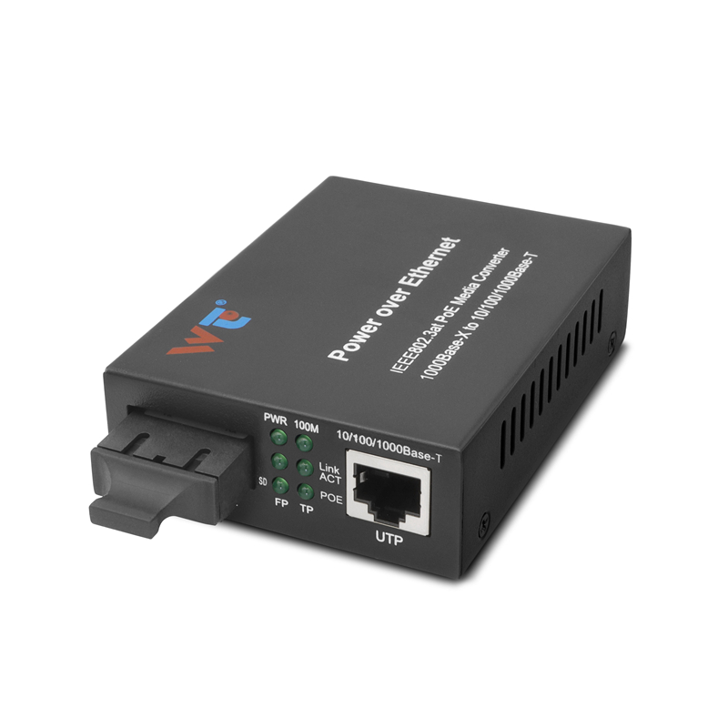
Required items are straightforward: PoE-capable IP cameras, a compatible PoE fiber media converter with SFP ports, single-mode or multimode fiber as dictated by distance, and a managed Edge switch. Industry terms to note include PoE (802.3af/at), SFP transceiver type, and VLAN tagging. For long runs prefer single-mode fiber and LC connectors; for short campus links multimode OM3/OM4 may suffice. Remember: copper Ethernet limits you to roughly 100 metres, while fiber extends to kilometres—this distinction drives the converter choice.
Step-by-step technical setup
1) Confirm power budget: calculate camera wattage against the converter’s PoE class and PSE capability. 2) Insert the correct SFP module for single-mode or multimode fiber. 3) Physically terminate fiber and verify continuity and optical loss with an OTDR or power meter. 4) Connect camera to the converter’s Ethernet port and ensure link LEDs indicate proper PHY speed. 5) Configure VLANs and trunking on the Edge switch so camera traffic is isolated into its intended VLAN. 6) If required, configure LLDP or port-based PoE timers on the switch to manage power sequencing. Keep MTU consistent between the converter and the Edge switch to avoid fragmentation.
Common mistakes and how to avoid them
Operators routinely underestimate three items: optical budget, PoE class mismatch, and management-plane access. Optical budget errors cause intermittent link drops; PoE class mismatch leaves cameras unpowered; poor management access prevents remote firmware and status checks—each has a straightforward remedy. Calibrate the optical budget with the specific SFP pair and include connector loss; match the converter’s PoE output to the camera’s inrush and sustained wattage; allow an out-of-band console or serial path for management during commissioning—this is prudent, not optional. —A short aside: maintain a simple change log at the site to record SFP part numbers and serials.
Testing and validation
Execute a three-stage verification: physical (fiber loss, connector integrity), electrical (PoE voltage under load, PSE negotiation), and network (throughput, latency, packet loss). Use packet captures at the Edge to confirm VLAN tagging and to verify RTP streams for CCTV. Target acceptance metrics: sub-5 ms additional latency from converter insertion, sustained video stream at expected bitrate without retransmissions, and stable PoE voltage within ±5% under peak draw. Document all test results for future troubleshooting.
Alternatives and trade-offs
If fiber termination or SFP logistics are constrained, consider hardened PoE extenders or cell-backhaul solutions, but these typically trade reach for bandwidth or increase latency. Conversely, active fiber switches at remote cabinets offer managed features but raise cost and power requirements. The chosen path should reflect deployment scale, maintenance capability, and lifecycle expectations.
Advisory: golden rules for procurement and deployment
– Verify end-to-end power and optical budgets before purchase; require vendor-provided loss tables for chosen SFPs.
– Insist on a standardized configuration template: VLAN tags, SNMP credentials, NTP and syslog destinations to ensure consistent device behaviour.
– Prioritize remote management and firmware update capability; a remotely unmanageable node becomes a field visit and an operational cost.
Conclusion
Following this framework reduces ambiguity and accelerates commissioning times while preserving forensic traceability of decisions. The practical tests and procurement rules above yield measurable improvements in uptime and mean time to repair. WINTOP. —technical clarity matters.